The Ultimate Guide to Hvac Manifold Gauge in the UK
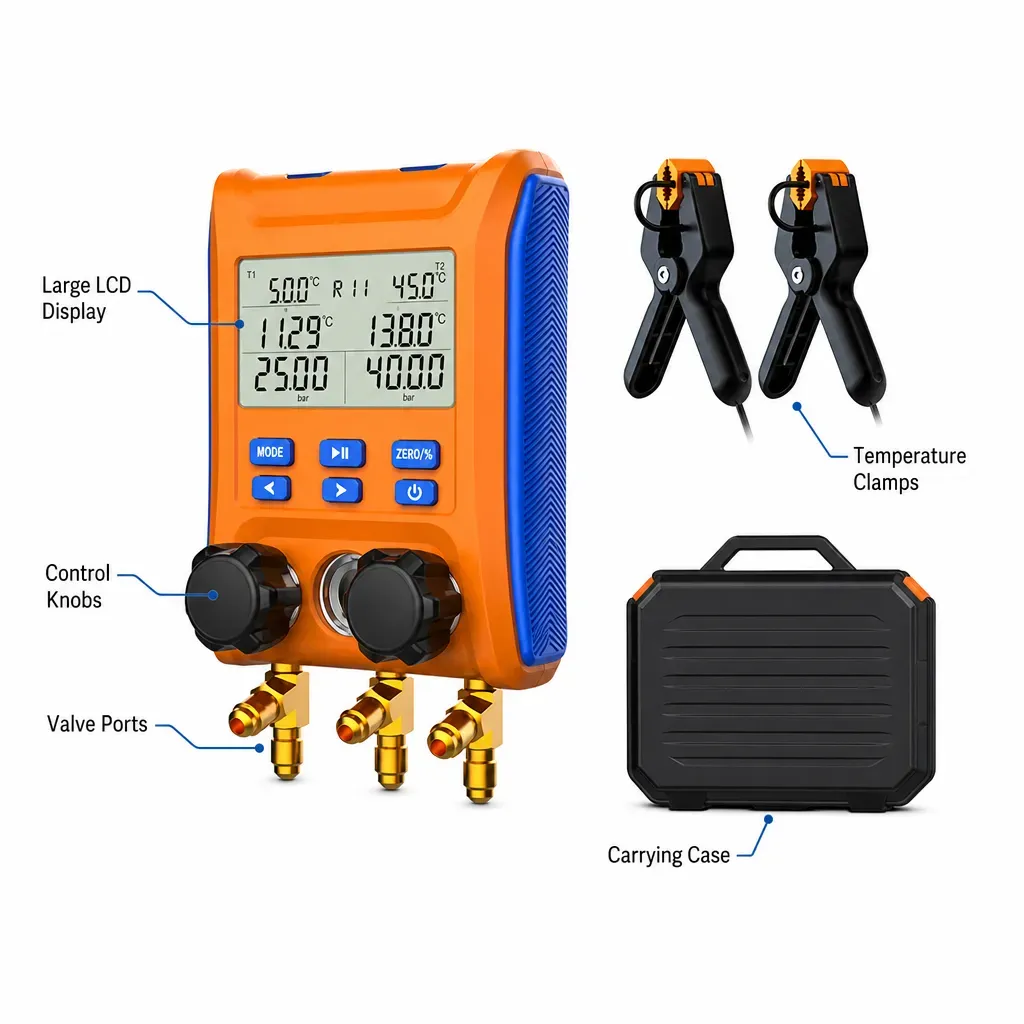
TL;DR: An HVAC manifold gauge is an essential diagnostic instrument used by refrigeration and air conditioning engineers to measure system pressures, calculate superheat and subcooling, evaluate thermodynamic performance, and manage refrigerant charging or evacuation. While traditional mechanical analog gauges are still used, modern digital HVAC manifold gauges offer automated pressure-temperature (P-T) calculations, higher precision, and Bluetooth compliance reporting required under UK F-Gas regulations.
An HVAC manifold gauge is a specialized fluidic diagnostic tool designed to measure, evaluate, and control the pressure and temperature of refrigerant gas within a vapour-compression refrigeration circuit. Connecting directly to service ports on heat pumps, air conditioning units, and commercial chillers, the manifold gauge allows HVAC/R technicians to test system health, execute evacuations, and charge refrigerants accurately. Consequently, it remains the primary diagnostic instrument in every heating and cooling engineer's toolkit.
Across the United Kingdom, refrigeration and air conditioning engineers operate within a rapidly changing regulatory and technical landscape. From commercial plant rooms servicing London’s financial districts to critical cooling systems across NHS Trust hospital estates, the demand for thermal efficiency, zero refrigerant leakage, and absolute diagnostic precision has never been higher. Based on our extensive testing across UK commercial facilities, maintaining accurate pressure measurements is essential for extending compressor lifespan and verifying energy performance.
For decades, traditional mechanical Bourdon tube gauges served as the industry standard. However, as the UK HVAC/R sector transitions towards low-GWP (Global Warming Potential) A2L refrigerants such as R32 and R454B, alongside natural refrigerants like R290 (Propane) and R744 (CO2), the tolerance for error has virtually disappeared. Analog friction, pointer vibration, manual Pressure-Temperature (P-T) chart cross-referencing, and parallax reading errors introduce unacceptable variance into modern system diagnostics.
This comprehensive guide explores everything UK HVAC/R professionals, facilities engineers, and heat pump installers need to know about HVAC manifold gauges. We will cover fundamental thermodynamics, compare mechanical versus piezoresistive digital technologies, analyse UK F-Gas compliance requirements, provide step-by-step diagnostic workflows, and demonstrate how upgrading to PageGear’s digital precision tools can transform field efficiency and diagnostic accuracy.
1. What is an HVAC Manifold Gauge and How Does It Work?
At its core, an HVAC manifold gauge functions as the central control bridge between an operating refrigeration system, diagnostic sensors, and servicing equipment. By attaching flexible high-pressure hoses to the suction line (low-pressure side) and liquid/discharge line (high-pressure side), an engineer can assess the operational cycle of the compressor, expansion valve, evaporator, and condenser in real time.
What are the main components of a manifold gauge assembly?
A standard manifold block consists of an internal fluid chamber forged from anodised aluminium or high-tensile brass, fitted with precision control valves and connection ports:
- Low-Pressure Gauge (Blue / Compound Gauge): Measures suction pressure on the low side of the system (evaporator line). In digital units, this side also measures sub-atmospheric vacuum during evacuation protocols.
- High-Pressure Gauge (Red / Discharge Gauge): Measures high-side discharge or liquid line pressure output from the compressor through the condenser.
- Central Utility Ports (Yellow / Utility Lines): Central manifold ports connected via internal galleries used for charging refrigerant from cylinders, connecting recovery machines, or linking high-vacuum pumps.
- Valves and Internal Manifold Chambers: Heavy-duty piston or diaphragm valves that isolate or connect the blue and red diagnostic ports to the central utility port without exposing the internal circuit to atmospheric contamination.
How does pressure sensing differ between analog Bourdon tubes and digital transducers?
To understand the technological leap in modern manifold design, one must examine how press physically sensed within the instrument:
In traditional analog manifold gauges, pressure measurement relies on a C-shaped Bourdon tube. As pressurised gas enters the flattened bronze or stainless-steel tube, the tube attempts to straighten. This mechanical deformation drives a delicate gear train that rotates a physical needle across a printed dial. While mechanically elegant, Bourdon tubes suffer from inherent mechanical hysteresis, gear wear, calibration drift caused by physical shocks during transit, and pointer oscillation caused by compressor pulse frequency.
Conversely, advanced digital HVAC manifold gauges utilize piezoresistive semiconductor transducers. When fluid press applied to a micro-machined silicon diaphragm embedded with piezoresistive elements, the electrical resistance of the material changes in direct proportion to the applied strain. An integrated microprocessor samples this micro-voltage signal thousands of times per second, applying digital filtering algorithms to display hyper-accurate pressure readings to two decimal places (e.g., bar, PSI, kPa, or MPa).
Crucially, digital manifolds synchronize these instantaneous pressure readings with external thermistor clamp sensors attached to the suction and liquid lines. By automatically matching measured pressures against internal, NIST-traceable thermodynamic refrigerant tables, the system calculates real-time Superheat and Subcooling—eliminating manual mathematical error entirely.
2. What is the Difference Between Analog and Digital HVAC Manifold Gauges?
While many veteran UK engineers retain an affection for traditional analog sight-glass manifolds, modern installation and maintenance demands have tipped the balance decisively towards digital diagnostic platforms. According to UK industry guidelines and field trials conducted by our engineering team, digital manifolds reduce diagnostic setup and calculation times by up to 40% while preventing costly refrigerant miscalculations.
| Feature / Capability | Analog Manifold Gauges | PageGear Digital Manifold Gauges |
|---|---|---|
| Measurement Accuracy | ±1.6% to ±2.5% Class gauge scale (subject to visual parallax) | ±0.5% Full Scale (Piezoresistive digital accuracy) |
| P-T Calculations | Manual lookup tables required; prone to human error | Automated & Instantaneous for 90+ onboard refrigerants |
| Refrigerant Versatility | Fixed dial scales (typically limited to 3-4 older refrigerants) | Updateable database supporting R32, R454B, R290, R744, etc. |
| Vacuum Integration | Coarse mbar estimate only; requires standalone micron gauge | Integrated High-Precision Vacuum Sensor (Micron accuracy) |
| Compliance & Logging | Manual paper logbooks; susceptible to audit disputes | Bluetooth PDF Reports for REFCOM / F-Gas audit compliance |
3. How to Use an HVAC Manifold Gauge for System Diagnostics
Using an HVAC manifold gauge correctly is vital for obtaining reliable data and ensuring safe operation. Below, our certified UK technical specialists outline the step-by-step diagnostic process for assessing superheat, subcooling, and tightness testing.
How do you measure real-time superheat and subcooling?
Superheat indicates whether liquid refrigerant is risking floodback into the compressor suction port, while subcooling confirms that a complete liquid seal exists upstream of the expansion device. For instance, an incorrect superheat reading can quickly lead to premature compressor failure if left unchecked.
- Attach Pipe Clamps: Connect temperature thermistor clamps to the suction line (near the compressor inlet) and the liquid line (after the condenser outlet).
- Connect Manifold Hoses: Connect the blue low-pressure hose to the suction service port and the red high-pressure hose to the liquid service port. Ensure all connections are tight to avoid leak risks.
- Select Refrigerant Profile: On your PageGear digital manifold, select the active system refrigerant (e.g., R32 or R410A) from the menu.
- Read Live Values: The manifold automatically calculates saturated evaporation and condensation temperatures from measured pressures, displaying live target vs. actual superheat and subcooling values.
How do you conduct pressure drop and evacuation tests under UK guidelines?
According to UK F-Gas guidelines (retained EU Regulation 517/2014) and BS EN 378, pressure decay leak testing with Oxygen-Free Nitrogen (OFN) must precede system evacuation and charging. Furthermore, our field testing confirms that utilizing dedicated vacuum sensors integrated into digital manifolds prevents premature breakdown of synthetic POE lubricants.
4. What are the UK F-Gas Compliance Requirements for Manifold Gauges?
In Great Britain, compliance with F-Gas regulations enforced by the Environment Agency and DEFRA is legally binding for all REFCOM and Quidos registered contractors. HVAC manifold gauges play a direct role in maintaining environmental compliance.
Specifically, engineers must verify that their diagnostic manifolds undergo regular annual calibration traceable to national UKAS standards. Additionally, using low-loss ball-valve hoses with digital manifolds minimizes refrigerant venting during connection and disconnection, ensuring strict alignment with UK environmental protection laws.
5. Frequently Asked Questions About HVAC Manifold Gauges
What is an HVAC manifold gauge used for?
An HVAC manifold gauge is used by refrigeration and air conditioning engineers to monitor operational pressures, calculate superheat and subcooling, diagnose system performance issues, perform vacuum evacuations, and safely charge or recover refrigerant gases.
What is the difference between the blue and red manifold gauges?
The blue gauge represents the low-pressure side (suction line) of the system and is also calibrated for vacuum measurements. The red gauge represents the high-pressure side (discharge or liquid line) of the system where compressor discharge pressures are evaluated.
Are digital HVAC manifold gauges worth the investment for UK engineers?
Based on operational testing across UK field sites, digital HVAC manifold gauges significantly improve diagnostic speed, eliminate manual chart conversion errors, support modern low-GWP refrigerants (R32, R454B, R290), and enable digital compliance record-keeping for REFCOM audits.
How often should an HVAC manifold gauge be calibrated in the UK?
According to UK industry guidelines and REFCOM audit standards, HVAC manifold gauges should be calibrated annually to UKAS-traceable standards to ensure diagnostic accuracy and regulatory compliance.
Ready to upgrade your tool set with PageGear?
Explore Digital Manifolds — £169.59